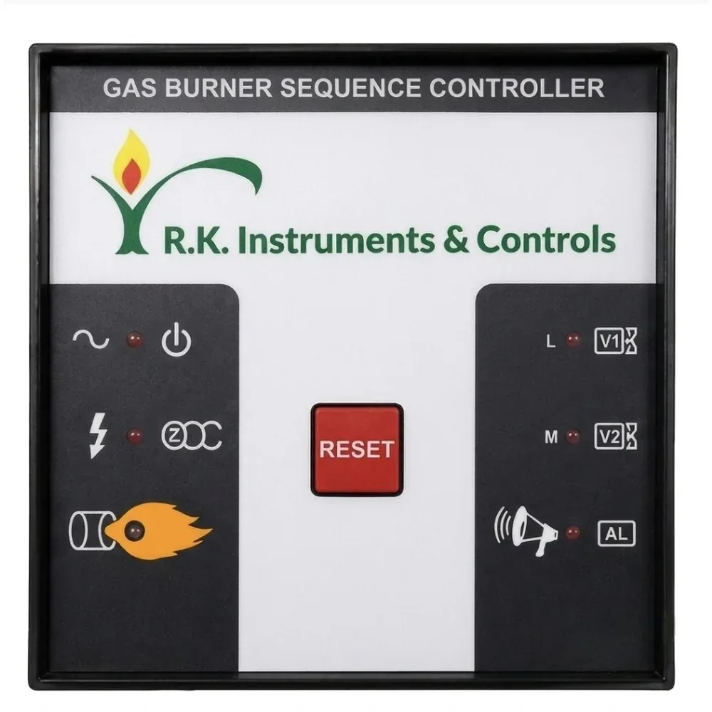
 Sequence Controller
The R.K. Instruments & Controls Gas Burner Sequence Controller is an in-house manufactured burner sequence controller for industrial gas-fired burners, operating on a 230 VAC supply. On power-up the Blower Motor (BL) output energizes immediately; after an 11-second pre-purge delay the Ignition Transformer (IG) output energizes, followed 1.5 seconds later by the low-flame Solenoid Valve (SV1) output. Flame is verified within milliseconds by a flame-rectification (ionization probe) sensing circuit — the built-in flame relay's NO/NC contacts remove the need for a separate external NC connection — and 12 seconds after flame is confirmed, the high-flame Solenoid Valve (SV2) output energizes for two-stage firing. If flame is not sensed, the controller enters Alarm/Lock Out mode, switching off the Ignition, SV1 and SV2 outputs and indicating burner-off on the Lock Out (LO) / alarm siren output; restart is via the front-panel manual RESET button, or an optional external reset terminal on request. Manufactured and supplied by R.K. Instruments & Controls for industrial gas-fired heating applications.
| Step | Action | Delay / Condition | Output / Status |
|---|---|---|---|
| 1 | Power ON | Input voltage 230V applied | Controller powered; Blower Motor (BL) output ON |
| 2 | Ignition ON | 11 sec after power ON | Ignition Transformer (IG) output ON |
| 3 | SV1 ON (Low Flame) | 1.5 sec after Ignition ON | Solenoid Valve 1 output ON |
| 4 | Flame Sensing | Milliseconds after SV1 ON | Flame detected; flame indication ON |
| 5 | SV2 ON (High Flame) | 12 sec after flame is sensed | Solenoid Valve 2 output ON |
| 6 | Alarm / Lock Out | If no flame is sensed | Ignition, SV1 & SV2 outputs OFF; Lock Out (LO) + alarm siren, burner-off indication |
| 7 | Restart | Manual RESET button, or external reset terminal (on request) | System restarts from Step 1 |
Note: The flame-sensing relay's NO/NC contacts are inbuilt, so no separate external NC wiring is required. All timings are approximate and can be customized as per process requirements.

| Terminal | Function |
|---|---|
| L | Line — 230V AC supply input |
| N | Neutral |
| BL | Blower Motor output |
| IG | Ignition Transformer output |
| SV1 | Solenoid Valve output — Low Flame (Stage 1) |
| LO | Lock Out / Alarm Siren output — indicates Burner Off (marked “S” on the flame-sensing schematic) |
| SV2 | Solenoid Valve output — High Flame (Stage 2) |
| FL | Flame Sensing — flame-rectification (ionization) probe input |
| Earthing | Ground/earth reference for the flame-sensing circuit (marked “R” on the flame-sensing schematic) — compulsory connection for safe operation |






























We represent the sales & service of these manufacturers across our territories.

 Brahma
 Cofi
Cofi Danfoss
 Dungs
Dungs Elektrogas
 Honeywell Eclipse
 Honeywell Elster
 Honeywell Kromschröder
 Honeywell Maxon
 Honeywell Technologies
 Madas
Madas R.K. Instruments & Controls
 Siemens
 Vanaz
Vanaz